how loft conversions work
Loft conversions are a common way to develop and existing property, this short guide summaries how they are built, how they are modified, and what needs to be considered.
DISCLAIMER: The below is intended as a general explainer of some of the issues that need to be considered, Loft conversions are complex operations which need qualified and experienced professionals to undertake (Architects, Structural Engineers, and Contactors). These works are not to be undertaken by homeowners or non-qualified persons. All lofts are different and no reliance on this information is offered.

Typical loft structural arrangement for a Victorian terrace building
EXISTING CONSTRUCTION
The image above details the most common loft construction found in London Victorian properties.
Anatomy
The timber ridge beam (light grey) at the apex of the roof unifies the sloping timber rafters (green), which are themselves supported by the purlins and diagonal struts (blue) in their centre and the masonry outer walls at their base.
A significant force is exserted on the purlins and diagonal struts by the rafters, this force is in turn transferred to the ceiling joists (dark grey) which is supported by the spine wall (yellow) in the centre of the building. Depending on the exact roof geometry the diagonal struts rest directly on the spine wall.
Load Paths
The approximate load path can be seen below shown in red arrows, it can be seen that the majority of the roof weight is being supported by central purlins, diagonal struts and spine wall.

Typical loft structural arrangement for a Victorian terrace building showing approximate load path
In the development of the loft space it is these diagonal struts which will need to be removed to allow uninterrupted use of the loft space, consequently some new support will need to be introduced.
Existing Ceiling Joists
The existing ceiling joist where constructed to support lightweight loft storage which in modern terms would be below 50kg/m2, as this ceiling will now become a floor supporting all the activities common in a home this floor will need to be reinforced to support a minimum of 150kg/m2 and in most cases 250kg/m2 in accordance with the current codes of practice. This ceiling/floor will also now be required to meet a range of other criteria such as increased fire performance, acoustic performance, thermal resistance, etc.
Central Spine Wall
Spine walls are typically 100mm thick brick or timber stud walls (sometimes with brick infill between the studs) with an additional layer of plasterboard either side resulting in an approximately 150mm thick spine wall. Despite the fact there are millions of these spine walls around the country that are clearly sufficient to support the existing loads they can generally not be justified to modern codes of practice, as a result it is often assumed that while the wall does not need reinforcing it cannot be used to support more weight than it already supports. Consequently, the new loft floor is typically supported on steel beams which avoid increasing the load on central spine wall.
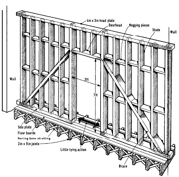
Typical timber stud spine wall with opening (ref: CIRIA 111)
PROPOSED CONSTRUCTION
There are many ways to approach a loft conversion but a 3-beam loft conversion is perhaps the most common as shown below. While this kind of conversion may have more than 3 beams and often a column, the name refers to the 3 parallel steel beams, one at the roof ridge level, one under the ashlar wall, and one around the middle of the floor space.

Typical 3-beam converted loft structural arrangement for a Victorian terrace building
The Ridge Beam and the Rear Dormer
The existing ridge beam is typically a relatively small timber beam which does the job of connecting the sloping timber rafters of the pitched roof together, this arrangement has the rafters leaning against each other in a house of cards fashion without a significant demand being being put upon the ridge beam itself.
In the below image you can assumes that the red and blue frames prop off each other at the ridge level, with the green ridge beam acting as a connecting plate rather than a traditional beam supporting all the loads vertically. These prop forces travel down the rafters and into the supporting timber and masonry at the lower level

Typical existing loads at ridge beam level
The reason this is important is because when we want to add a rear dormer to gain additional standing space as shown below we have to cut the existing sloped rafters at the rear of the property, removing these rafters on one side creates an imbalance, which is remedied with a steel ridge beam designed to support both the sloped and flat part of the new roof.

Additional rear dormer shown in green
Ridge Beam Support without Chimney
As this new arrangement had more load being supported by the ridge beam, this is a relatively straightforward matter if most cases as shown below. A new concrete padstone sized to spread the additional stress is set into the shared party wall but remaining entirely within the owners half of the wall (i.e. no new construction strays over the notional line which runs along the centreline of the wall dividing the owners and neighbours half of the wall thickness.).

Additional rear dormer shown in green
Ridge Beam Support with Chimney
Where the new ridge beam connects to the chimney this is more problematic as the chimney is often in a poor condition and not able to support the loads without extensive testing (which is normally expensive and time consuming). There are a number of support strategies, 3 of which are detailed here:
Option 1: Column Proud of Chimney

Op 1: Column Proud of Chimney
This is the most cost effective and low risk option owning to the fact that alterations to the chimney are substantively not required, avoiding any risks associated with the existing condition. Additionally this also means the chimney flues can remain active if a smokeless wood burner are being proposed (or similar). The compromise is that the post is set against the face of the chimney which will intrude into the usable space by approximately 100mm. This can be incorporated into cupboards or joinery but it is not always seen as an ideal solution. The steel column is supported by a piece of trimming steel which is supported by the main steelwork as shown above.
Option 2: Column Inset into Chimney

Op 2: Column Inset into Chimney
Alternatively, the column can he hidden within the depth of the chimney as shown above, this has the benefit of hiding the column but can be fairly difficult to build (resulting in a higher cost), as well as obstructing the use of the chimneys.
If this option is to be selected it is important that the Contractor undertaking the works is experienced in this kind of work and appoints a suitably qualified temporary works engineer to ensure the chimney above is sufficiently propped during the works. If this is done incorrectly the chimney can topple, chimney may weigh over a metric ton and may fall through the house all the way to the ground floor.
Option 3: Steel Rafters

Op 3: Steel Rafters
This option has no column but has additional steelwork hidden within the roof profile, the additional steel tonnage and connections can increase upfront costs but it will generally deliver a more usable space, allow the expression of the chimney breast, and can be used in combination with the removal of the chimney breast within the loft space (though note that this typically presents some project specific additional challenges not discussed here).
Ashlar Beam
The exact position of the ashlar beam can be critical to the design of the loft more generally as it needs to both support the ashlar wall (short timber stud wall supporting the front rafters) and avoid overstressing the chimney flues which is partially rest on, this position is defined by the engineer following carful measurement and and design.

Section through loft showing beam names and approximate positions
Midfloor Beam
A midfloor beam is typically position at the edge of the new stair opening and reduces the maximum span of the timber joists in the new floor. shorter spans mean shallower joists which in turn means more headroom, it is important to get the position of the stairs correct to avoid using more material and reducing headroom. As with the ashlar beam the position of this beam will be defined by the Architect and Engineer after careful design.
SUMMARY
The above is a short guide to some of the key decision and constraints when converting a loft, please refer to the other guides for more detail on the various consideration.